

-
Products

-
-
-
After-sale Service
Installation precautions for the safety valve of a three-lobe rotary blower
Release time:
2022-06-11
The safety valve of the three-lobe rotary blower should be installed upright and close to the protected equipment or pipeline. If it cannot be arranged close by, the total pressure drop from the protected equipment or pipeline to the safety valve inlet should not exceed 3% of the safety valve set pressure. A maintenance platform should be set up for the safety valve of the three-lobe rotary blower. When arranging heavy safety valves, consider the possibility of hoisting after disassembly, and a lifting rod should be provided if necessary. The inlet pipeline of the safety valve of the three-lobe rotary blower should use long-radius elbows. The design of the outlet pipeline of the safety valve of the three-lobe rotary blower should consider that the back pressure does not exceed a certain value of the safety valve set pressure. For ordinary spring-type safety valves, the back pressure should not exceed 10% of the safety valve set pressure. When the medium discharged into the venting main pipe or the flare main pipe contains condensate or condensable gases, the outlet of the safety valve should be higher than the main pipe; otherwise, liquid drainage measures should be taken. The outlet pipeline of the safety valve discharging into a closed system should be connected at a 45° angle to the top of the discharge main pipe in the direction of the medium flow to prevent condensate in the main pipe from flowing back into the branch pipe, and to reduce the back pressure of the safety valve. When there are shut-off valves on the inlet and outlet pipelines of the three-lobe rotary blower safety valve, a single gate valve should be selected, and it should be sealed with lead, with the valve rod installed horizontally to prevent the pin connecting the valve rod and the valve plate from corroding or loosening, causing the valve plate to slide down. When the safety valve is equipped with a bypass valve, this valve should be sealed closed.
The safety valve of the three-lobe Roots blower should be installed upright and close to the protected equipment or pipeline. If it cannot be arranged close by, the total pressure drop in the pipeline from the protected equipment or pipeline to the safety valve inlet should not exceed 3% of the safety valve set pressure. A maintenance platform should be set up for the safety valve of the three-lobe Roots blower. When arranging heavy safety valves, consider the possibility of hoisting after disassembly, and a lifting rod should be provided if necessary. The inlet pipeline of the safety valve of the three-lobe Roots blower should use long radius elbows. The design of the outlet pipeline of the safety valve of the three-lobe Roots blower should consider that the back pressure does not exceed a certain value of the safety valve set pressure. For ordinary spring-type safety valves, the back pressure should not exceed 10% of the safety valve set pressure. When the medium discharged into the venting main pipe or the flare main pipe contains condensate or condensable gases, the outlet of the safety valve should be higher than the main pipe; otherwise, liquid drainage measures should be taken.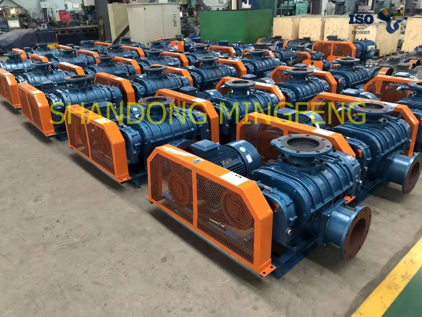 The outlet pipeline of the safety valve discharging into a closed system should be connected at a 45° angle to the top of the discharge main pipe in the direction of the medium flow, to prevent condensate in the main pipe from flowing back into the branch pipe, and to reduce the back pressure of the safety valve. When there are shut-off valves on the inlet and outlet pipelines of the three-lobe Roots blower safety valve, a single gate valve should be selected, and it should be sealed with lead, with the valve stem installed horizontally, to prevent corrosion or loosening of the pin connecting the valve stem and the valve plate, which could cause the valve plate to slide down. When the safety valve is equipped with a bypass valve, that valve should be sealed closed.
Key words:

Submit information now to obtain the total solution of wind turbine
To provide users with high-quality products and convenient pre-sale, sale and after-sales service, reflecting the "Ming Feng" to make users satisfied with the whole process of service.
No. 1-3, West First Road North, Fenghuangshan Industrial Park, Puji Street, Zhangqiu District, Jinan City, Shandong Province
Free service hotline